with Answers, Solution | Semiconductor Electronics | Physics - Exercise Numerical Problems | 12th Physics : UNIT 10a : Semiconductor Electronics
Chapter: 12th Physics : UNIT 10a : Semiconductor Electronics
Exercise Numerical Problems
Numerical Problems
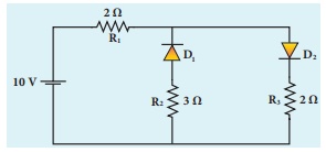
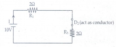
1. The given circuit has two ideal diodes connected as shown in figure below. Calculate the current flowing through the resistance R1 [Ans: 2.5 A]
Solution:
Barrier
potential for ideal diode is zero. The diode D1 is reverse biased,
so it will block the current and diode D2 is forward biased, so it
will pass the current.
The
given circuit becomes
Effective
resistance Reff = R1 + R3 = 4╬®
Current through R1 = V/Reff = 10/4 = 2.5A
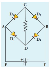
2. Four silicon diodes and a 10 ╬® resistor are connected as shown in figure below. Each diode has a resistance of 1╬®. Find the current flows through the 18╬® resistor. [Ans: 0.13 A]
Solution:
In
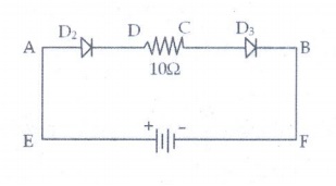
the given circuit D2 & D3 are in forward bias so they
conduct current while D1 &D4 are in reverse bias so
they do not conduct current. So the equivalents circuit will be
the
effective resistance is Reff
=
1╬® + 10╬® + 1╬® = 12╬®
Here
silicon diodes are used
Ōł┤ Barrier potential for Si is 0.7
V
Net
potential (Vnet) = 3 ŌĆō 0.7 - 0.7
Vnet
= 1.6 V
Current (I) = Vnet / R eff = 1.6 / 12 = 0.133A
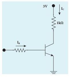
3. Assuming VCEsat = 0.2 V and ╬▓ = 50, find the minimum base current (IB) required to drive the transistor given in the figure to saturation. [Ans: 56 ┬ĄA]
Solution;
VCE
= 0.2V
Rc
= 1k╬®
╬▓
=50
Vcc
= 3V
I
B = ?
Ic
= [ VCC ŌĆō VCE ] / RC
=
(3-0.2) / 103
=
2.8 ├Ś 10-3 A
=
2.8 mA
╬▓=
IC/IB
Ōł┤ IB = IC /
╬▓ = 2.8 ├Ś 10-3 / 50 = 0.056├Ś 10-3
=
56 ├Ś 10-6 A
IB=56╬╝A
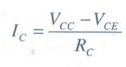
4. A transistor having ╬▒ =0.99 and VBE = 0.7V, is given in the circuit. Find the value of the collector current.
[Ans: 5.33 mA]
Given data:
╬▒
=0.99
VBE
= 0.7V
IC=?
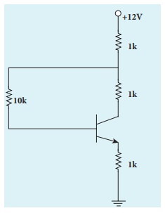
Solution:
Tranistor
is in saturation region.
Ōł┤ Ic = Ic(sat)
IC
and IB are independent
VCE(sat)
= 0.2 V, VBE(sat) = 0.8 V for silicon transistor (ie, standard
value)
Apply KVR across B-E loop:
V1k
+ V10k + VBE sat + V1k = VCC
Ōł┤ 1(IC + IB)
+ 10 IB + 0.8 + 1 (IC + IB) = 12
2
IC + 12 IB = 11.2 ŌĆ”ŌĆ”ŌĆ”ŌĆ”ŌĆ”(1)
Apply KVR across C-E loop:
V1k
+ V1k + VCE sat + V1k = VCC
l(IC
+ IB) + 1 IC + 0.2 + I(IC + IB) =
12
3IC
+ 2IB = 11.8 ŌĆ”ŌĆ”ŌĆ”ŌĆ”ŌĆ”ŌĆ”.(2)
Solve
the equation (1) and (2)
IB
= 0.3125 mA
IC = 3.725 mA Ōēł 3.73 mA
5. In the circuit shown in the figure, the BJT has a current gain (╬▓) of 50. For an emitter ŌĆō base voltage VEB = 600 mV, calculate the emitter ŌĆō collector voltage VEC (in volts). [Ans: 2 V]
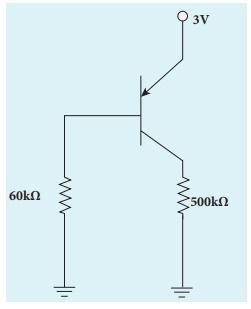
Given data:
╬▓ = 50
VE=3V
VEB=60
mV
RB=60K╬®
RE=500╬®
Solution:
VB=VEŌłÆVEB
VB
= 3ŌłÆ0.6 = 2.4V
IB
= VB/RB = 2.4 / 60├Ś103 = 40╬╝A
IC
= ╬▓IB = 50├Ś40╬╝A = 2├Ś10-3 A = 2mA
VC
= RCIC = 500├Ś2├Ś10-3 = 1V
VEC
= VE-VC = 3-1 = 2V
VEC = 2V
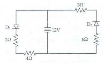
6. Determine the
current flowing through 3╬® and 4╬® resistors of the circuit given below. Assume
that diodes D1 and D2 are ideal diodes.
Solution:
The
diode D2 is in reverse biased. So does not conduct current.
Ōł┤ current through 3╬® is = 0
The
diode D1 is in forward biased, and it is an ideal diode. So the
given circuit becomes as
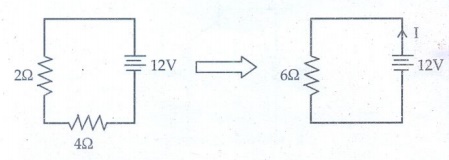
The
current through 4╬® is
Ōł┤ I
= V/R = 12/6 =2A
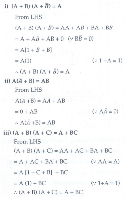
7. Prove the
following Boolean expressions using the laws and theorems of Boolean algebra.
i)
(A + B) (A + ![]() ) = A
) = A
ii)
A (![]() +B) = AB
+B) = AB
iii)
(A + B) (A + C) = A + BC
Solution:
8. Verify the given
Boolean equation A + ߊ╣B = A + B using
truth table.
Solution:
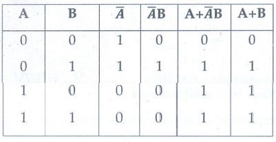
Hence,
verified
9. In the given
figure of a voltage regulator, a Zener diode of breakdown voltage 15V is employed.
Determine the current through the load resistance, the total current and the
current through the diode. Use diode approximation.
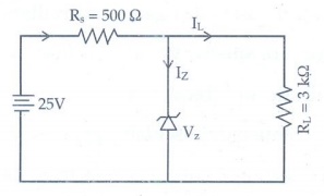
Solution:
Voltage
across RL(VO) = Vz = 15V
Voltage across RS(VRS) =
25 -15 = 10V
current
through RL is
IL
= V0/RL = 15 / 3├Ś103 = 5├Ś10-3 A
IL
= 5 mA
Current
through RS is
I
= VRS/RS = 10/500 = 20├Ś10-3A
I
= 20mA
Current
through Zener diode is
IZ=I-IL
=
(20-5) ├Ś
10-3
Iz
= 15mA
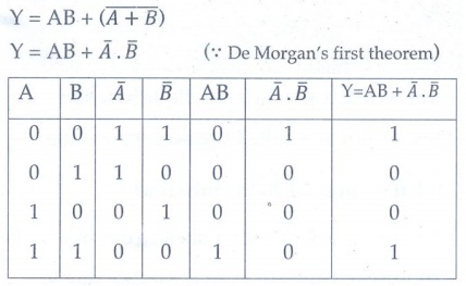
10. Write down
Boolean equation for the output Y of the given circuit and give its truth
table.
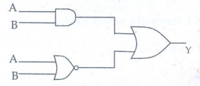
Solution:
Related Topics